

CONTENTS
FOREWORD 9
INTRODUCTION 12
1Scope 14
2Normative references 15
3Terms, definitions, symbols and abbreviated terms 18
3.1Terms and definitions 18
3.2Symbols and abbreviated terms 18
4Normal and special environmental conditions 19
4.1General 19
4.2Normal environmental conditions 20
4.2.1Ambient air temperature 20
4.2.2Altitude 20
4.2.3Vibrations or earth tremors 20
4.2.4Exposure to pollution 20
4.2.5Other environmental conditions for indoor instrument transformers 20
4.2.6Other environmental
conditions for outdoor instrument transformers 21
4.2.7IT with outdoor parts 21
4.3Special environmental conditions 21
4.3.1General 21
4.3.2Altitude 21
4.3.3Ambient temperature 21
4.3.4Vibrations or earth tremors 22
4.3.5Earthquakes 22
5Ratings 22
5.1General 22
5.2Voltage ratings 22
5.2.1Highest voltage for equipment (Um) 22
5.2.2Power system earthing 25
5.2.3Standard values for rated primary voltage (Upr) 25
5.2.4Standard values for rated secondary voltage (Usr) 25
5.2.5Rated auxiliary power supply voltage (Uar) 25
5.3Current ratings 26
5.3.1Standard values for rated primary current (Ipr) 26
5.3.2Standard values for rated secondary current (Isr) 26
5.3.3Standard values for rated continuous thermal current (Icth) 26
5.3.4Short-time current ratings 26
5.4Dielectric ratings 27
5.4.1General 27
5.4.2Rated primary terminal insulation level 27
5.4.3Other requirements for primary terminal insulation 27
5.4.4Between-section insulation requirements 29
5.4.5Insulation requirements for secondary terminals and low-voltage components 29
5.5Rated frequency (fr) 30
Output ratings 30
5.6.1Rated output for inductive instrument transformers and CVTs 30
5.6.2Rated burden for LPITs 30
5.6.3Standard values for the rated delay time for EITs (tdr) 30
5.7Accuracy requirements 30
5.7.1General 30
5.7.2Rated accuracy classes 31
5.7.3Accuracy class extension for harmonics 31
5.7.4Accuracy requirements for harmonics 31
5.7.5Harmonic requirements for LPIT protection accuracy classes 34
5.7.6Anti-aliasing filter for EIT using digital data processing 34
6Design and construction 36
6.1Requirements for liquids used in equipment 36
6.1.1General 36
6.1.2Liquid quality 36
6.1.3Liquid level indicator 37
6.1.4Liquid tightness 37
6.2Requirements for gases used in equipment 37
6.2.1General 37
6.2.2Gas quality 37
6.2.3Gas monitoring device 37
6.2.4Gas tightness 37
6.2.5Pressure-relief device 38
6.3Requirements for solid materials used in equipment 38
6.4Requirements for temperature rise of parts and components 38
6.4.1General 38
6.4.2Influence of altitude on temperature rise 40
6.5Requirements for earthing of equipment 41
6.5.1General 41
6.5.2Earthing of the enclosure 41
6.5.3Electrical continuity 41
6.6Requirements for the external insulation 41
6.6.1Pollution 41
6.6.2Altitude 42
6.7Mechanical requirements 43
6.8Multiple chopped impulses on primary terminals 44
6.9Internal arc fault protection requirements 45
6.10Degrees of protection by enclosures 45
6.10.1General 45
6.10.2Protection against access to hazardous parts and protection of the equipment against ingress of solid foreign objects and water 45
6.10.3Protection of enclosure against mechanical impact under normal
operating conditions 46
6.11Electromagnetic compatibility (EMC) 46
6.11.1General 46
6.11.2Requirements for immunity 46
6.11.3Requirements for emission 50
6.11.4Requirements for transmitted overvoltage (TOV) 50
6.11.5Requirements for radio interference voltage (RIV) 50
6.12Corrosion 50
6.13Markings 50
6.13.1General 50
6.13.2Terminal markings 51
6.13.3Rating plate markings 51
6.14Requirements for LPIT secondary terminal connection 52
6.14.1Requirements for digital output connection 52
6.14.2Requirements for analogue output connections 53
6.15EIT secondary signal noise 54
6.16Fire hazard 55
6.17Pressure withstand of gas-filled enclosures 55
6.18Failure detection of EIT 55
6.19Operability 55
6.20Reliability and dependability of electronic part of EIT 55
6.21Vibration requirements 56
6.22Storage climatic conditions withstand capability 56
7Tests 56
7.1General 56
7.1.1Classification of tests 56
7.1.2List of tests 57
7.1.3Sequence of tests 58
7.1.4Testing conditions 60
7.2Type tests 60
7.2.1General 60
7.2.2Temperature rise test 61
7.2.3Impulse voltage withstand test on primary terminals 62
7.2.4Wet test for outdoor type instrument transformers 65
7.2.5Electromagnetic compatibility (EMC) tests 66
7.2.6Tests for accuracy 71
7.2.7Verification of the degree of protection by enclosures 74
7.2.8Enclosure tightness test at ambient temperature 74
7.2.9Proof test for the gas-filled enclosure 74
7.2.10Mechanical tests 75
7.2.11Voltage withstand test of low-voltage components and secondary
terminals 76
7.2.12Storage climatic environmental tests 77
7.2.13Vibration test 79
7.2.14Durability of markings 80
7.2.15Tests for accuracy for harmonics 80
7.2.16Test for anti-aliasing 81
7.3Routine tests 81
7.3.1Power-frequency voltage withstand test on primary terminals 81
7.3.2Partial discharge measurement 82
7.3.3Power-frequency voltage withstand tests between sections 84
7.3.4Power-frequency voltage withstand tests on secondary terminals 85
7.3.5Power-frequency voltage withstand test for low-voltage components 85
7.3.6Test for accuracy 85
7.3.7Verification of markings 86
7.3.8Enclosure tightness test at ambient temperature 86
7.3.9Pressure test for the gas-filled enclosure 86
7.3.10Measurement of capacitance and dielectric dissipation factor 87
7.4Special tests 87
7.4.1Multiple chopped impulse test on primary terminals 87
7.4.2Transmitted overvoltage test 88
7.4.3Internal arc fault test 92
7.4.4Enclosure tightness test at low and high temperatures 93
7.4.5Insulation resistance measurement on secondary terminals 94
7.4.6Corrosion test 94
7.4.7Fire hazard test 94
7.4.8Thermo-mechanical endurance test 95
7.4.9Vibration and shock tests 95
7.4.10Tests for accuracy versus harmonics 98
7.4.11Seismic qualification 98
7.5Commissioning tests 98
7.5.1General 98
7.5.2Final installation inspection and tests 98
7.5.3Gas dew point test 99
7.6Sample tests 99
8Rules for transport, storage, erection, operation and maintenance 99
8.1General 99
8.2Conditions during transport, storage and installation 99
8.3Installation 99
8.3.1General 99
8.3.2Unpacking and lifting 99
8.3.3Assembly 100
8.3.4Mounting 100
8.3.5Connections 100
8.3.6Final installation inspection and tests 100
8.4Operation 101
8.5Maintenance 101
8.5.1General 101
8.5.2Responsibilities for the manufacturer 101
8.5.3Responsibilities for the user 101
8.6Failure report 102
9Safety 102
10Influence of products on the natural environment 102
Annex A (normative) Identification of test specimen 103
A.1General 103
A.2Data 103
A.3Drawings 103
Annex B (informative) Recommendation for contents of failure reports 104
B.1General 104
B.2Content 104
Annex C (informative) Fire hazard 106
C.1Fire hazard 106
C.2Fire hazard test 106
Annex D (informative) Sample test 107
D.1Sample test definition 107
D.2Sample tests 107
Annex E (informative) Technique used in temperature rise test of transformers to
determine the thermal time constant by an experimental estimation 108
Annex F (informative) Guidance for the extension of validity of type tests or special
tests of instrument transformers 111
F.1General 111
F.2Information needed for extension of type test validity 111
F.3Application of extension criteria 112
F.3.1Dielectric tests 112
F.3.2Temperature rise tests 112
F.3.3Short-time and dynamic withstand current tests (current transformers) 113
F.3.4Internal arc fault tests 114
F.3.5Multiple chopped impulse test 114
Annex G (informative) Guidance for the calculation of equivalent diameter in case of
irregular shape of insulating part 116
G.1General 116
G.2Current transformers and earthed voltage transformers 116
G.3Unearthed voltage transformers 117
Annex H (informative) Test circuits 119
H.1Test circuits for accuracy measurements in steady state for current
transformers with analogue secondary signal 119
H.2Test circuits for accuracy measurements in steady state for voltage
transformers with analogue secondary signal 123
Annex I (normative) Seismic qualification of instrument transformers 127
I.1Scope 127
I.2Seismic conditions 127
I.2.1Time-history 127
I.2.2Seismic severity of application 127
I.2.3Superelevation factor (kse) 129
I.3Seismic qualification information 129
I.3.1Qualification options 129
I.3.2General information provided by purchaser 129
I.4Qualification procedure 129
I.4.1General 129
I.4.2Qualification by static calculation or dynamic analysis 130
I.4.3Qualification by test 137
I.5Validity of qualification 139
Bibliography 140
Figure 1 – General block diagram of single-phase LPITs 14
Figure 2 – Example of digital data acquisition system 34
Figure 3 – Example of frequency response mask for EIT with digital output 36
Figure 4 – Altitude correction factor for the temperature rise 40
Figure 5 – Factor m for the switching impulse voltage (USIL) withstand test 43
Figure 6 – Example structure used in HV AIS applications subjected to EMC tests 48
Figure 7 – Example of structure used in HV GIS applications subjected to EMC tests 49
Figure 8 – Duplex LC connector 53
Figure 9 – RIV measuring circuit 66
Figure 10 – Temperature cycle accuracy test 73
Figure 11 – Test circuit for partial discharge measurement 82
Figure 12 – Alternative circuit for partial discharge measurement 83
Figure 13 – Example of balanced test circuit for partial discharge measurement 83
Figure 14 – Voltage profile for partial discharge measurement 84
Figure 15 – Transmitted overvoltage measurement: test impulse waveforms 89
Figure 16 – Transmitted overvoltage measurement: primary test configuration for AIS
equipment 90
Figure 17 – Transmitted overvoltage measurement: primary test configuration for GISs
(CTs and VTs) 90
Figure 18 – Transmitted overvoltage measurement: example of correct secondary test
connection for CT and VT 91
Figure 19 – Typical configuration for internal arc fault test 92
Figure E.1 – Graphical extrapolation to ultimate temperature rise 110
Figure G.1 – Shed dimensions 116
Figure G.2 – Examples of MV CTs and earthed VTs 117
Figure G.3 – Example of a CT with multiple insulator areas 117
Figure G.4 – Examples of unearthed VTs 118
Figure G.5 – Example of a VT with multiple insulator areas 118
Figure H.1 – Test circuit for accuracy measurements of inductive CTs 119
Figure H.2 – Test circuit for analogue accuracy measurements of LPCTs 120
Figure H.3 – Test circuit for analogue accuracy measurements of LPCTs (alternative
solution) 121
Figure H.4 – Test circuit for digital accuracy measurements of LPCTs 122
Figure H.5 – Test circuit for accuracy measurements of inductive VTs or CVTs 123
Figure H.6 – Test circuit for analogue accuracy measurements of LPVTs 124
Figure H.7 – Test circuit for analogue accuracy measurements of LPVTs (alternative
solution) 125
Figure H.8 – Test circuit for digital accuracy measurements of LPVTs 126
Figure I.1 – Record of time-history in real (3 dimensional) 127
Figure I.2 – Required response spectrum 128
Figure I.3 – Flowchart of qualification procedure 130
Figure I.4 – Measured deflection in free oscillation 132
Figure I.5 – Sketch of the parameters in static calculation 134
Table 1 – Operating ambient temperature categories 20
Table 2 – Rated primary terminal insulation levels for instrument transformers for AC
applications 24
Table 3 – Insulation requirements for power supply terminals 26
Table 4 – Partial discharge test voltages and permissible levels for AC applications 28
Table 5 – Maximum values of tanδ 29
Table 6 – LPIT secondary terminal and low-voltage component terminal withstand
capability 29
Table 7 – WB0 extension for harmonics 32
Table 8 – Accuracy class extensions for wide bandwidth applications 33
Table 9 – Harmonic requirements for protection accuracy classes 34
Table 10 – Anti-aliasing filter requirements 35
Table 11 – Permissible temporary leakage rates for gas systems 38
Table 12 – Limits of temperature and temperature rise for various parts, materials and
dielectrics of instrument transformers 39
Table 13 – Specific creepage distances by site pollution severity class, as defined in
the former publication 42
Table 14 – Maximum static withstand loads 44
Table 15 – Maximum gas-in-oil level in instrument transformers 44
Table 16 – Arc fault duration and performance criteria 45
Table 17 – Immunity requirements and test levels 47
Table 18 – Acceptance criteria for EMC immunity tests 49
Table 19 – Connectors 54
Table 20 – List of tests 57
Table 21 – Gas type and pressure during tests 58
Table 22 – Required routine tests 59
Table 23 – Modalities of application of the test loads to be applied to the primary
terminals 76
Table 24 – Dry heat test, storage temperature 78
Table 25 – Cold test, storage temperature 78
Table 26 – Damp heat steady state test 79
Table 27 – Transmitted overvoltage limits 89
Table 28 – Shock severity levels 97
Table A.1 – Example of drawing to be submitted 103
Table C.1 – Fire hazard of electrotechnical products 106
Table F.1 – Extension criteria for dielectric withstand performance 112
Table F.2 – Extension criteria for temperature rise performance 113
Table F.3 – Extension criteria for short-time and dynamic withstand current
performance 113
Table F.4 – Extension criteria for internal arc fault tests 114
Table F.5 – Extension criteria for multiple chopped impulse test 115
Table I.1 – Seismic severity levels 128
Table I.2 – External mass to simulate external forces 137
Table I.3 – Comparable seismic levels 139
Product family standard | Product standard | Title |
61869-1 General requirements | 61869-2 | Additional requirements for current transformers |
61869-3 | Additional requirements for inductive voltage transformers | |
61869-4 | Additional requirements for combined transformers | |
61869-5 | Additional requirements for capacitor voltage transformers | |
61869-7 | Additional requirements for low-power voltage transformers | |
61869-8 | Additional requirements for low-power current transformers | |
61869-9 | Digital interface for instrument transformers | |
61869-10 | Additional requirements for current sensors | |
61869-11 | Additional requirements for voltage sensors | |
61869-12 | Additional requirements for combined low-power instrument transformers | |
61869-13 | Stand-alone merging unit (SAMU) | |
61869-14 | Additional requirements for current transformers for DC applications | |
61869-15 | Additional requirements for voltage transformers for DC applications | |
61869-16 | TEDS (transducer electronic data sheet) for instrument transformers | |
61869-99 | Glossary |
INSTRUMENT TRANSFORMERS –
Part 1: General requirements
1 Scope
This part of IEC 61869 is applicable to newly manufactured instrument transformers intended for applications where the nominal voltage is higher than 1 kV AC or 1,5 kV DC, with an analogue or a digital secondary signal for measuring, protection and control purposes, with rated frequencies from 15 Hz to 400 Hz, or for DC applications.
NOTE 1 A bushing type current transformer, although having no primary insulation level for itself is often placed on a system with a nominal voltage > 1 kV AC or > 1,5 kV DC and therefore falls within the scope of this document. Example: CT placed around an HV bushing or a cable.
The general requirements for instrument transformers for applications in LV systems (nominal voltage ≤ 1 kV AC or ≤ 1,5 kV DC) are covered by IEC 61869-201.
This part of IEC 61869 is a product family standard and covers general requirements only. For each type of instrument transformer, the product standard is composed of this document and the relevant specific product standard.
This part of IEC 61869 contains the requirements for the limits of the errors both for analogue and digital secondary signals. The other characteristics of a digital interface for instrument transformer are standardised in IEC 61869-9 as an application of the IEC 61850 horizontal standard series, covering communication networks and systems for power utility automation.
This part of IEC 61869 considers bandwidth requirements. The accuracy requirements on harmonics and requirements for the anti-aliasing filter are specified in 5.7.
In the case of an LPIT, the general block diagram of single-phase devices is given in Figure 1.
According to the technology, it is not always necessary that all parts described in Figure 1 be included in the instrument transformer.
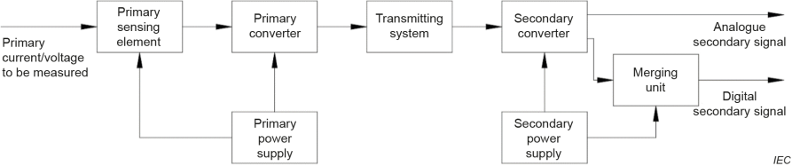
Figure 1 – General block diagram of single-phase LPITs
2 Normative references
The following documents are referred to in the text in such a way that some or all of their content constitutes requirements of this document. For dated references, only the edition cited applies. For undated references, the latest edition of the referenced document (including any amendments) applies.
IEC 60060-1, High-voltage test techniques – Part 1: General definitions and test requirements
IEC 60068-2-1, Environmental testing – Part 2-1: Tests – Test A: Cold
IEC 60068-2-2:2007, Environmental testing – Part 2-2: Tests – Test B: Dry heat
IEC 60068-2-6, Environmental testing – Part 2-6: Tests – Test Fc: Vibration (sinusoidal)
IEC 60068-2-11, Environmental testing – Part 2-11: Tests – Test Ka: Salt mist
IEC 60068-2-17, Basic environmental testing procedures – Part 2-17: Tests – Test Q: Sealing
IEC 60068-2-27:2008, Environmental testing – Part 2-27: Tests – Test Ea and guidance: Shock
IEC 60068-2-47, Environmental testing – Part 2-47: Tests – Mounting of specimens for vibration impact and similar dynamic tests
IEC 60068-2-57:2013, Environmental testing – Part 2-57: Tests – Test Ff: Vibration – Time- history and sine-beat method
IEC 60068-2-75, Environmental testing – Part 2-75: Tests – Test Eh: Hammer tests
IEC 60068-2-78:2012, Environmental testing – Part 2-78: Tests – Test Cab: Damp heat, steady state
IEC 60068-3-3:2019, Environmental testing – Part 3-3: Supporting documentation and guidance
– Seismic test methods for equipment
IEC 60071-1:2019, Insulation co-ordination – Part 1: Definitions, principles and rules
IEC 60071-2:2018, Insulation co-ordination – Part 2: Application guidelines
IEC 60085, Electrical insulation – Thermal evaluation and designation
IEC 60270:2000, High-voltage test techniques – Partial discharge measurements
IEC 60270:2000/AMD1:2015
IEC 60296, Fluids for electrotechnical applications – Mineral insulating oils for electrical equipment
IEC 60376, Specification of technical grade sulphur hexafluoride (SF6) and complementary gases to be used in its mixtures for use in electrical equipment
IEC 60455 (all parts), Resin based reactive compounds used for electrical insulation
IEC 60475, Method of sampling insulating liquids
IEC 60480, Specifications for the re-use of sulphur hexafluoride (SF6) and its mixtures in electrical equipment
IEC 60529:1989, Degrees of protection provided by enclosures (IP Code)
IEC 60529:1989/AMD1:1999
IEC 60529:1989/AMD2:2013
IEC 60603-7-1, Connectors for electronic equipment – Part 7-1: Detail specification for 8-way, shielded, free and fixed connectors
IEC 60695-1-10, Fire hazard testing – Part 1-10: Guidance for assessing the fire hazard of electrotechnical products – General guidelines
IEC 60695-1-11, Fire hazard testing – Part 1-11: Guidance for assessing the fire hazard of electrotechnical products – Fire hazard assessment
IEC 60794-2:2017, Optical fibre cables – Part 2: Indoor cables – Sectional specification
IEC 60794-3, Optical fibre cables – Part 3: Outdoor cables – Sectional specification
IEC TS 60815-1:2008, Selection and dimensioning of high-voltage insulators intended for use in polluted conditions – Part 1: Definitions, information and general principles
IEC TS 60815-2:2008, Selection and dimensioning of high-voltage insulators intended for use in polluted conditions – Part 2: Ceramic and glass insulators for a.c. systems
IEC TS 60815-3:2008, Selection and dimensioning of high-voltage insulators intended for use in polluted conditions – Part 3: Polymer insulators for a.c. systems
IEC 60867, Insulating liquids – Specifications for unused liquids based on synthetic aromatic hydrocarbons
IEC TR 61000-4-1, Electromagnetic compatibility (EMC) – Part 4-1: Testing and measurement techniques – Overview of IEC 61000-4 series
IEC 61000-4-2, Electromagnetic compatibility (EMC) – Part 4-2: Testing and measurement techniques – Electrostatic discharge immunity test
IEC 61000-4-3, Electromagnetic compatibility (EMC) – Part 4-3: Testing and measurement techniques – Radiated, radio-frequency, electromagnetic field immunity test
IEC 61000-4-4, Electromagnetic compatibility (EMC) – Part 4-4: Testing and measurement techniques – Electrical fast transient/burst immunity test
IEC 61000-4-5:2014, Electromagnetic compatibility (EMC) – Part 4-5: Testing and measurement techniques – Surge immunity test
IEC 61000-4-5:2014/AMD1:2017
IEC 61000-4-6, Electromagnetic compatibility (EMC) – Part 4-6: Testing and measurement techniques – Immunity to conducted disturbances, induced by radio-frequency fields
IEC 61000-4-8, Electromagnetic compatibility (EMC) – Part 4-8: Testing and measurement techniques – Power frequency magnetic field immunity test
IEC 61000-4-9, Electromagnetic compatibility (EMC) – Part 4-9: Testing and measurement techniques – Impulse magnetic field immunity test
IEC 61000-4-10, Electromagnetic compatibility (EMC) – Part 4-10: Testing and measurement techniques – Damped oscillatory magnetic field immunity test
IEC 61000-4-11, Electromagnetic compatibility (EMC) – Part 4-11: Testing and measurement techniques – Voltage dips, short interruptions and voltage variations immunity tests for equipment with input current up to 16 A per phase
IEC 61000-4-13, Electromagnetic compatibility (EMC) – Part 4-13: Testing and measurement techniques – Harmonics and interharmonics including mains signalling at AC power port, low frequency immunity tests
IEC 61000-4-16, Electromagnetic compatibility (EMC) – Part 4-16: Testing and measurement techniques – Test for immunity to conducted, common mode disturbances in the frequency range 0 Hz to 150 kHz
IEC 61000-4-17, Electromagnetic compatibility (EMC) – Part 4-17: Testing and measurement techniques – Ripple on DC input power port immunity test
IEC 61000-4-18:2019, Electromagnetic compatibility (EMC) – Part 4-18: Testing and measurement techniques – Damped oscillatory wave immunity test
IEC 61000-4-29, Electromagnetic compatibility (EMC) – Part 4-29: Testing and measurement techniques – Voltage dips, short interruptions and voltage variations on DC input power port immunity tests
IEC 61000-6-4:2018, Electromagnetic compatibility (EMC) – Part 6-4: Generic standards – Emission standard for industrial environments
IEC 61076-2-101, Connectors for electronic equipment – Product requirements – Part 2-101: Circular connectors – Detail specification for M12 connectors with screw-locking
IEC 61083-1, Instruments and software used for measurement in high-voltage and high-current tests – Part 1: Requirements for instruments for impulse tests
IEC 61099, Insulating liquids – Specifications for unused synthetic organic esters for electrical purposes
IEC 61181, Mineral oil-filled electrical equipment – Application of dissolved gas analysis (DGA) to factory tests on electrical equipment
IEC 61462, Composite hollow insulators – Pressurized and unpressurized insulators for use in electrical equipment with rated voltage greater than 1 000 V – Definitions, test methods and acceptance criteria and design recommendations
IEC 61850-7-4, Communication networks and systems for power utility automation – Part 7-4: Basic communication structure – Compatible logical node classes and data object classes
IEC 61869-9:2016, Instrument transformers – Part 9: Digital interface for instrument transformers
IEC 61869-99, Instrument transformers: Glossary
IEC 62155, Hollow pressurized and unpressurized ceramic and glass insulators for use in electrical equipment with rated voltages greater than 1 000 V
IEC 62217:2012, Polymeric HV insulators for indoor and outdoor use – General definitions, test methods and acceptance criteria
IEC 62271-4:2022, High-voltage switchgear and controlgear – Part 4: Handling procedures for gases for insulation and/or switching
IEC 62271-100, High-voltage switchgear and controlgear – Part 100: Alternating-current circuit- breakers
IEC 62271-203:2022, High-voltage switchgear and controlgear – Part 203: Gas-insulated metal- enclosed switchgear for rated voltages above 52 kV
IEC 62770, Fluids for electrotechnical applications – Unused natural esters for transformers and similar electrical equipment
IEC 63012, Insulating liquids – Unused modified or blended esters for electrotechnical applications
CISPR TR 18-2, Radio interference characteristics of overhead power lines and high-voltage equipment – Part 2: Methods of measurement and procedure for determining limits
ISO/IEC/IEEE 21451-4, Information technology – Smart transducer interface for sensors and actuators – Part 4: Mixed-mode communication protocols and Transducer Electronic Data Sheet (TEDS) formats
ISO 4628-3, Paints and varnishes – Evaluation of degradation of coatings – Designation of quantity and size of defects, and of intensity of uniform changes in appearance – Part 3: Assessment of degree of rusting
ISO 22479, Corrosion of metals and alloys – Sulfur dioxide test in a humid atmosphere (fixed gas method)
Symbols and abbreviated terms
ADC | analogue-to-digital converter |
AIS | air-insulated switchgear |
CT | current transformer |
CVT | capacitor voltage transformer |
EIT | electronic IT |
EMC | electromagnetic compatibility |
F | mechanical load |
fr | rated frequency |
Frel | relative leakage rate |
FV | rated voltage factor |
GIS | gas-insulated switchgear |
Iarc | rated internal arc fault current |
Icth | rated continuous thermal current |
Idyn | rated dynamic current |
Ipr | rated primary current |
Ipsc | rated short-circuit current |
Isr | rated secondary current |
Ith | rated short-time thermal current |
IED | intelligent electronic device |
IT | instrument transformer |
Kr | rated transformation ratio |
kse | superelevation factor |
LPCT | low-power current transformer |
LPIT | low-power instrument transformer |
LPVT | low-power voltage transformer |
MU | merging unit |
PD | partial discharge |
RMS | root-mean-square |
SAMU | stand-alone merging unit |
Sr | rated output – rated output power |
tdr | rated delay time |
Um | highest voltage for equipment |
Upr | rated primary voltage |
Usr | rated secondary voltage |
Usys | highest voltage of the system |
VT | voltage transformer |
Zbr | rated burden |
ZPA | zero period acceleration |
∆φ | phase displacement |
ε | ratio error |
εc | composite error |
fe | phase error |
Bibliography
IEC 60044-8, Instrument transformers – Part 8: Electronic current transformers
IEC 60050-212:2010, International Electrotechnical Vocabulary (IEV) – Part 212: Electrical insulating solids, liquids and gases
IEC 60050-212:2010/AMD1:2015
IEC 60255-1:2009, Measuring relays and protection equipment – Part 1: Common requirements
IEC 60255-27:2013, Measuring relays and protection equipment – Part 27: Product safety requirements
IEC 60417, Graphical symbols for use on equipment (available at http://www.graphical- symbols.info/equipment)
IEC 60664-1, Insulation coordination for equipment within low-voltage supply systems – Part 1: Principles, requirements and tests
IEC 60695-1-30, Fire hazard testing – Part 1-30: Guidance for assessing the fire hazard of electrotechnical products – Preselection testing process – General guidelines
IEC 60695-7-1, Fire hazard testing – Part 7-1: Toxicity of fire effluent – General guidance
IEC 60721-2-6, Classification of environmental conditions – Part 2: Environmental conditions appearing in nature – Earthquake vibration and shock
IEC 60812, Failure modes and effects analysis (FMEA and FMECA)
IEC TR 60815:19865, Guide for the selection of insulators in respect of polluted conditions
IEC TR 60943, Guidance concerning the permissible temperature rise for parts of electrical equipment, in particular for terminals
IEC 61000 (all parts), Electromagnetic compatibility (EMC)
IEC 61000-4-7, Electromagnetic compatibility (EMC) – Part 4-7: Testing and measurement techniques – General guide on harmonics and interharmonics measurements and instrumentation, for power supply systems and equipment connected thereto
IEC TR 61000-5-6, Electromagnetic compatibility (EMC) – Part 5-6: Installation and mitigation guidelines – Mitigation of external EM influences
IEC 61000-6-5, Electromagnetic compatibility (EMC) – Part 6-5: Generic standards – Immunity for equipment used in power station and substation environment
IEC 61025, Fault tree analysis (FTA)
IEC 61754-2, Fibre optic connector interfaces – Part 2: Type BFOC/2,5 connector family
IEC 61754-20, Fibre optic interconnecting devices and passive components – Fibre optic connector interfaces – Part 20: Type LC connector family
IEC TR 61869-103:2012, Instrument transformers – The use of instrument transformers for power quality measurement
IEC 61869-16, TEDS (transducer electronic data sheet) for instrument transformers 6
IEC 62262, Degrees of protection provided by enclosures for electrical equipment against external mechanical impacts (IK code)
IEC 62271-1:2017, High-Voltage Switchgear and Controlgear – Part 1: Common specifications for alternating current switchgear and controlgear
IEC Guide 109, Environmental aspects – Inclusion in electrotechnical product standards
ISO/IEC/IEEE 8802-3, Telecommunications and exchange between information technology systems – Requirements for local and metropolitan area networks – Part 3: Standard for Ethernet
IEEE 693-2018, IEEE Recommended Practice for Seismic Design of Substations
EN 50160, Voltage characteristics of electricity supplied by public distribution systems
CIGRE Brochure 765, Understanding and mitigating corrosion