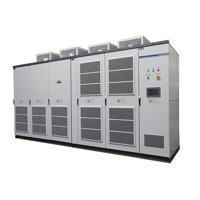
General Rating | 3.3–11 kV |
|
|
Input | Rated input voltage | Three-phase 50/60 Hz, 6 kV | Three-phase 50/60 Hz, 11 kV |
Voltage fluctuation | Full-load running at 6 kV/10 kV±10%; long-term running at –35% to –10% by applying derating |
Frequency range | 50 Hz±10% |
Input voltage of power cells | 690 V |
Input power factor | ≥ 0.95 (with load more than 20%) |
Input current harmonics | ≤ 4%, compliant with the IEEE 519-1992 |
Output | Output voltage range | 0–11 kV |
Output voltage of power cells | 690 V |
Output frequency range | 0–50 Hz; max. 720 Hz; above 120 Hz as customized product |
Speed regulation ratio | 40:1 (universal vector); 100:1 (SVC); 200:1 (FVC) |
Rotational speed accuracy | ±0.5 % (SVC); ± 0.2 % (FVC) |
Startup torque | 0.5 Hz/150% (SVC); 0 Hz/180% (FVC) |
Technical solution | Power cells connected in series, AC-DC-AC, and high voltage input and output |
Control mode | Universal vector and SVC or FVC |
Rectification | Diode three-phase full bridge |
Inversion | IGBT inverter bridge |
Acceleration and deceleration time | 0.1–6500s; > 6500s customizable |
Start/Stop control | Local or remote |
Control system | ARM, DSP, FPGA, and HMI |
Panel display | Touchscreen, English |
Overload capacity | 120% of rated current, 1 minute |
Efficiency | ≥ 96% |
Fuse equipped for the AC drive | A fuse on the input side of power cells |
Optical fiber adopted for the electrical isolation part | Yes |
Input filter required | No |
Output filter required | No |
Power factor compensation required | No |
Power cell protection | Overvoltage, undervoltage, input phase loss, overcurrent, overtemperature, and communication |
System protection | Motor overload, output overload, output short circuit, output grounding, input overcurrent, input overvoltage, input imbalance, input grounding, cooling fan fault alarm, door switch interlock protection, transformer overheat alarm, transformer overheat trip, and transformer secondary short circuit protection |
Mean time between failures (MTBF) | 50,000 hours |
Communication interface | Modbus-RTU, CANlink, Profibus-DP |
Digital input | 10 inputs, relay dry contact |
Digital output | 16 outputs, relay dry contact |
Analog input | 4 inputs, 4–20 mA or 0–10 V |
Analog output | 5 outputs, 4–20 mA or 0–10 V |
Service environment | Indoor |
Ambient temperature | –10°C to +40°C; derating at 40°C to 50°C; preheating before startup below –10°C |
Ambient humidity | 5–95%, non-condensing |
Altitude | ≤ 1000 m; derating at more than 1000 m. Specify the altitude when ordering. |
Total noise of equipment | ≤ 80dB |
Cooling | Forced air cooling |
IP rating | IP30 |
Cabinet type | GGD combined type |
Cable entry and exit method | Lower cable entry and exit, or customized configuration |
Control power supply | 380 V±10% AC, three-phase and four-wire |
